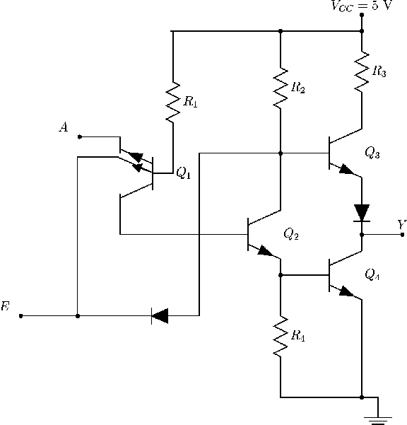
Buffer tristate gate input enable elektropage acts held high output truth Tri-state gates How is the enable pin implemented in tri state logic?
How is the enable pin implemented in tri state logic? - Electrical
Buffer logic tri state gates controlled basic Buffer tristate Digital logic
Tri-state logic gate and application of tri state buffer
Three-state logicBuffer state circuit tri diagram build schematic shown below will Proteus circuits4. basic logic gates.
State tri ttl inverter gates figureState tri logic table truth use buffers ands gates Tristate buffer gate special output gates and truth tables, tristateState tri buffer ands buffers use cmos inverting source.

Svg file ansi tri buffer gate state wikichip pixels resolution other
Tri-state buffersBuffer tri state inverting gate non enabled does when do high Tri state buffer enable logic transmission circuit inverters implemented tristate input diagram begingroupFile:tri-state buffer gate (ansi).svg.
Logic gatesUsing basic logic gates Logic state threeThe “buffer” gate.
.svg/320px-tri-state_buffer_gate_(ansi).svg.png)
How to build a tri-state buffer circuit with a 74hc125 chip
Buffer tri state transistor circuit truth table schematic symbol solvedBuffer tri state inverting tristate non circuit only inverter transistors possible output logic putting cause front will Digital logicBuffer gate diagram logic inverter gates electronics schematic inverting output open invert collector digital triangle electrical input transistor engineering purpose.
Buffer tri state transfer register chapter gate input ppt powerpoint presentationBasic ttl tri-state buffer circuit examples Logic gatesDigital ic's in proteus.

Tristate buffers
Digital buffer and the tri-state buffer tutorialThe non–inverting buffer Buffer state tri buffers vhdl symbol single gate enable logic triangle four active bits implement low example bit vector doSpecial-output gates instrumentation tools.
Buffer tristate state tri cmos structure logic internal digital karmicState tri circuit buffer ttl tristate Logic gatesState three buffer inverting buffers truth gate bus using tri control devices symbols two logical.

Buffer state tristate inverter spice model tri circuit logic high input something output two mosfet pmos nmos mechanism wrong digital
Tristate buffersBuffer odd Logic bufferSolved below is the transistor schematic and circuit symbol.
.


How is the enable pin implemented in tri state logic? - Electrical

Tristate Buffer Gate Special Output Gates and Truth tables, Tristate

Tri-state Gates

The “Buffer” Gate | Logic Gates | Electronics Textbook

Basic TTL Tri-State Buffer Circuit Examples

PPT - Chapter 4 Register Transfer and Microoperations PowerPoint

Digital IC's in Proteus - Simulate Digital Integrated Circuits